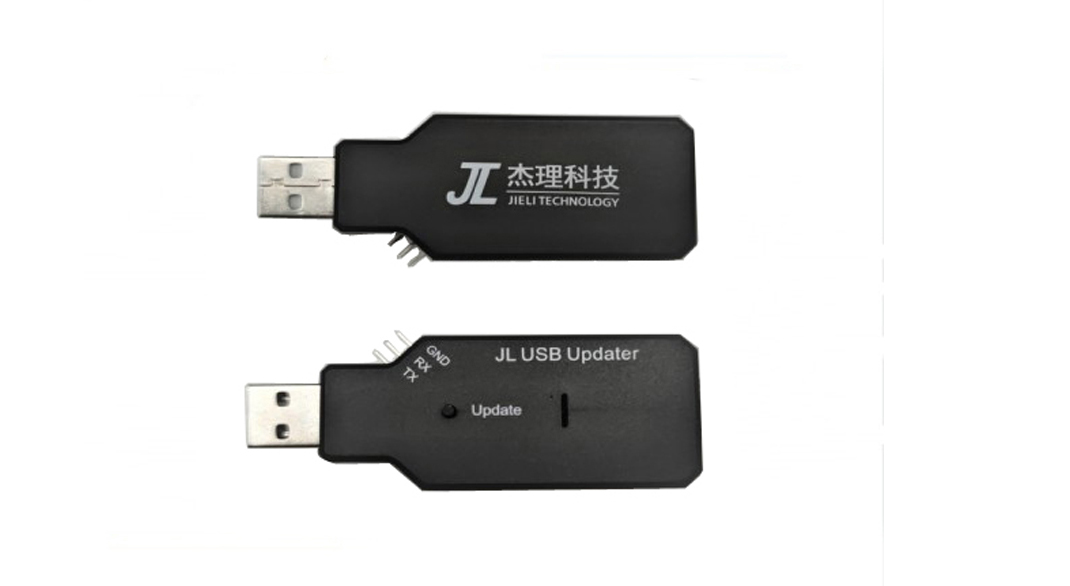
How to Use the JL USB Updater 4.0 Tool

(1) DIP switch lower four bits:
Not switched: Send USBkey, upgrade DV15, DV16, DV17, BR17, BR18, BR20, BR21, BR22 (non-A version).
Bit 1: Send USBkey, continuous mode.
Bit 2: Send ISPkey, upgrade BR22 (A version).
Bit 3: Reserved.
Bit 4: Reserved.
(2) DIP switch upper four bits:
Default state of the JL USB tool's output terminal determined by the 5th bit of the DIP switch:
Default state of the JL USB tool's output terminal determined by the 5th bit of the DIP switch:
Not switched: The DP and DM of the tool's output terminal are set to high impedance.
Bit 5: The DP and DM of the tool's output terminal are used for serial communication.
TX is always set to high impedance (RX of the prototype should be pulled up).
When the tool receives a command from the PC to set the baud rate:
(1) After setting the baud rate to 1, the serial port operates in full-duplex mode (default mode).
(2) After setting the baud rate to 2, the serial port operates in single-wire mode, where TX is used for both transmit and receive functions (currently used to support single-wire serial port upgrade chips).
(3) In single-wire mode, when the set baud rate is less than or equal to 9600, TX sends the UART key.
When the tool receives JTAG operation commands from the PC:
The DP and DM of the tool's output terminal are used for JTAG communication.
When the tool receives upgrade operation commands from the PC:
Equivalent to pressing the upgrade button, entering the upgrade process.
When the tool receives flash operation commands from the PC:
The DP and DM of the tool's output terminal are used for flash operation (after the flash operation is completed, it automatically returns to the default state).
The RX pin on the tool is connected to the CS pin of the flash.
The DP pin on the tool is connected to the CLK pin of the flash.
When the tool receives a command from the PC to set the baud rate:
(1) After setting the baud rate to 1, the serial port operates in full-duplex mode (default mode).
(2) After setting the baud rate to 2, the serial port operates in single-wire mode, where TX is used for both transmit and receive functions (currently used to support single-wire serial port upgrade chips).
(3) In single-wire mode, when the set baud rate is less than or equal to 9600, TX sends the UART key.
The DM pin on the tool is connected to both the DO and DI pins of the flash.
These pins are already routed to the 10-pin JTAG interface on the tool.
If you want to operate the on-chip flash of SH50, switch the 6th bit of the DIP switch.
The tool's enum is "SH50 Burn v1.0.0."
Tool's self-requirements:
Bit 7: The tool upgrades itself.
Bit 8: After entering upgrade mode, it will not automatically exit upgrade mode.
(3) Upgrade operation:
Upgrade directly by pressing the tool's button.
After the prototype enters upgrade mode, it can be exited by pressing the tool's button again.
(4) LED status Indication:
When the tool is powered on, the red and green LEDs flash simultaneously.
Under normal conditions, the red LED is constantly on, and the green LED is blinking.
When the tool's button is pressed, both the red and green LEDs are constantly on.
When the prototype enters upgrade mode, the red LED is constantly on, and the green LED is off.
When JTAG connection fails, both the red and green LEDs will flash (due to sdtap command timeout or CRC error, please lower the communication rate).


 MCU Solutions
 PCBA Solutions
 FAQ
FAQ Contact Us
 Company News
 MCU News
 PCBA News
 Company Profile
 Certificates
 Terms & Conditions
 Privacy Statement


 More information?


